
What Causes Signal Loss in Coaxial Cable?
Dielectric and conductor losses: Energy dissipation in the cable core and insulation
When signals travel through coaxial cables, they start losing strength because of basic energy loss mechanisms. The main wire inside the cable actually loses some power as electrons bump into each other in the metal structure. This gets worse at higher frequencies when most of the current flows only near the outer part of the conductor, not throughout its entire thickness. At the same time, the plastic insulation between conductors also plays a role. It grabs some of the electromagnetic waves passing through and turns them into heat instead of letting them reach their destination. These two problems combined usually cause about three quarters of all signal weakening in regular cable setups. That's why long runs of coax can sometimes result in weaker reception or lower quality connections.
Frequency-dependent attenuation: Why higher RF frequencies increase coaxial cable loss
The amount of signal loss goes way up as frequencies get higher because of how electromagnetic waves behave. When we look at frequencies above 100 MHz, each time the frequency doubles, there's about a 30% increase in signal loss through RG-6 cables. This happens mainly because electrons tend to travel closer to the surface (skin effect) and the insulation material reacts more strongly to the changing electric fields. Take a standard 100 foot length of RG-6 cable for instance. At 1 GHz it loses around 6.5 dB of signal strength, while down at 50 MHz it only drops about 1.2 dB. Given these differences, picking the right cable becomes really important when dealing with modern high speed networks such as 5G installations or DOCSIS 3.1 internet services where even small losses can impact performance significantly.
Impedance mismatch and reflections: How VSWR undermines signal integrity in coaxial cable
Mismatch between coaxial cable impedance (usually around 50 ohms or 75 ohms) and what's connected at either end leads to those pesky signal reflections we all hate. What happens next? Those bouncing signals get in the way of the main signal coming through, which creates these standing wave patterns that engineers measure using something called Voltage Standing Wave Ratio or VSWR for short. When this ratio goes over about 1.5 to 1, things start going wrong pretty fast. Signal quality drops by roughly 3 decibels, and equipment might just stop working properly now and then. Why does this happen? Well, there are several usual suspects: connectors that weren't crimped correctly during installation, connections that have started to rust or corrode over time, and cables that got bent too sharply somewhere along their run. The worst part? These reflections don't just sit there quietly. They actually make the normal losses in the cable worse, so instead of getting full power transmission, systems might only be transferring about 60% of what they should be when everything matches up properly.
Physical and Installation Factors That Amplify Coaxial Cable Loss
Cable length and attenuation: Calculating dB loss per foot for common coaxial cable types
Signal attenuation scales directly with cable length due to conductor resistance and dielectric absorption. Longer runs amplify energy loss, converting RF signals into heat. For example:
- RG-6 loses roughly 0.25 dB/ft at 750 MHz
- LMR-400 maintains 0.11 dB/ft at 1 GHz
This exponential relationship necessitates precise pre-installation calculations–always reference manufacturer attenuation charts for your target frequency range.
Bending, crushing, and shielding damage: Invisible threats to coaxial cable performance
Physical stress during installation degrades performance in ways often overlooked:
- Sharp bends exceeding the minimum bend radius distort the dielectric geometry, increasing impedance mismatch
- Compressed shielding reduces interference rejection by up to 40%
-
Kinked conductors create localized reflection points
Moisture ingress through damaged jacketing accelerates oxidation, raising conductor resistance. Best practices include maintaining bend radii greater than 10× the cable diameter and avoiding torsion during routing.
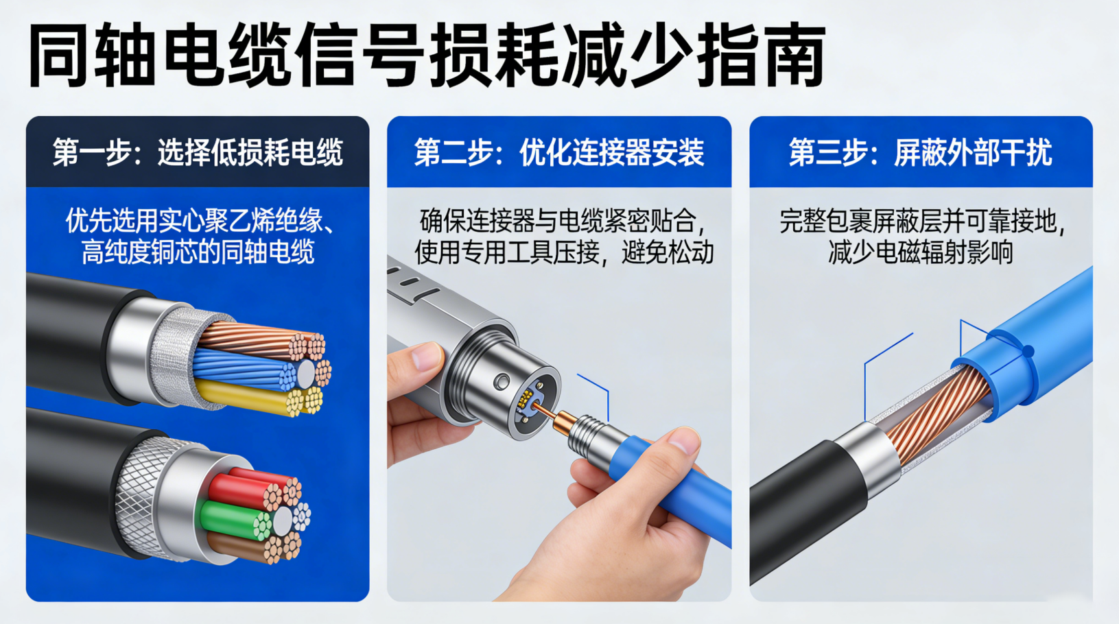
Proven Strategies to Minimize Signal Loss in Coaxial Cable Systems
Choosing low-loss coaxial cable: Copper vs. CCA, foam vs. solid dielectric, and shielding effectiveness
Choosing the right coaxial cable really comes down to finding the sweet spot between how well it conducts electricity, what kind of dielectric material is used, and how good the shielding is. When looking at conductors, solid copper beats copper clad aluminum (CCA) hands down when it comes to signal loss. We're talking about around 20 to 30 percent less attenuation because plain old copper just conducts better through its entire structure. Foam filled dielectrics make a big difference too. These can cut down on those pesky capacitance losses by as much as 40% compared to regular solid polyethylene since they don't let electrons bounce around so much inside the insulation. If electromagnetic interference is a concern, quad shield designs with multiple layers of aluminum foil and braided shielding are the way to go. They keep signal leakage under 1%, which makes them pretty much standard equipment in serious RF applications. And dont forget about impedance stability either. Quality cables stay within plus or minus 2 ohms across different frequencies, which means signals stay clean and consistent no matter what band theyre operating on.
Precision termination and connector selection: Eliminating impedance discontinuities and corrosion in coaxial cable links
Getting connectors right stops most of those annoying impedance reflections that mess with VSWR readings. Compression style connectors keep things tight within about half a millimeter when installed properly, which helps maintain that important 50 or 75 ohm impedance across connections. Gold plating on contact surfaces really matters too since it fights off oxidation problems especially bad in damp areas where resistance tends to creep up around 15 to 20 percent each year according to some studies. For installations facing harsh conditions or out in the elements, going with stainless steel connectors featuring IP68 rated seals makes sense as they stop water from getting inside, something that causes lots of those frustrating intermittent failures we all hate. Before wrapping up any project, it pays to check how well terminations are done using TDR testing equipment. This detects tiny flaws at the micron level that could otherwise lead to bigger headaches down the road once everything is deployed for good.