
Impedance Matching and Frequency Band Compatibility
Why 50 Ω Is Critical for BTS RF Interfaces
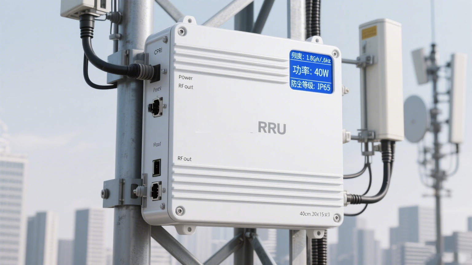
The Base Transceiver Station (BTS) systems depend heavily on maintaining a standard 50 ohm impedance throughout their RF interfaces. This helps get the most out of power transfers while keeping those annoying signal reflections at bay. International RF engineering standards like IEC 61196 and IEEE 1162 actually specify this requirement, which makes sure everything works together properly when connecting antennas, filters, amplifiers and those long transmission lines we all know and love. When there are mismatches beyond plus or minus 5 ohms, around 15 to 30 percent of the transmitted power gets reflected back instead of going where it should. That kind of thing really messes with signal quality and causes problems with Voltage Standing Wave Ratio measurements. And let's face it, in today's cellular networks operating at these incredibly high frequencies, small deviations just keep getting worse as they propagate through the system. So sticking strictly to that 50 ohm standard isn't just good practice anymore it's absolutely necessary if we want our network deployments to stay both stable and able to scale up when needed.
Performance Requirements Across HF/VHF/UHF and Cellular Bands (700 MHz–2.7 GHz)
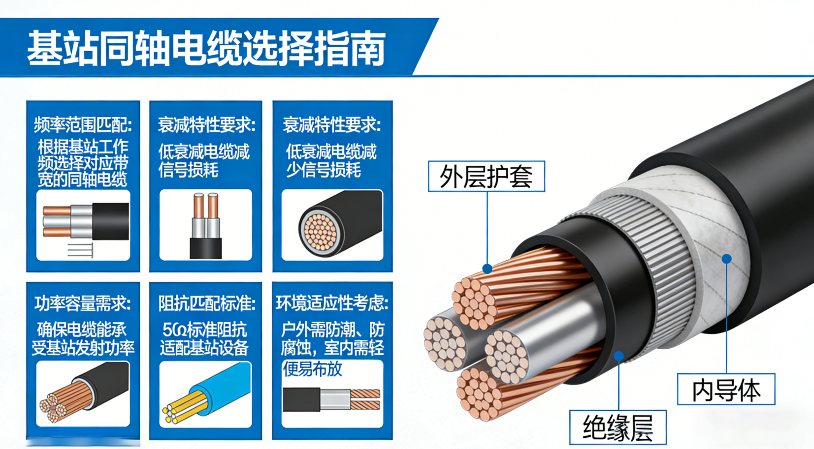
For coaxial cables to work properly, they need to keep that steady 50 ohm impedance throughout their operation while also performing well within specific frequency bands. When we look at HF and VHF frequencies between roughly 3 to 300 megahertz, what matters most is maintaining stable phase characteristics and minimizing signal dispersion. This becomes particularly important for older systems still using analog voice communications and legacy data transmission methods. Things change quite a bit when moving into UHF and modern cellular spectrum around 700 MHz all the way up to about 2.7 GHz. Here the focus shifts toward reducing signal loss and ensuring the cable can handle substantial power levels. This is especially true with today's 5G networks that require such wide bandwidths and those complicated massive MIMO setups. Interestingly enough, a cable designed specifically for operation at 2.7 GHz might actually lose around 40 percent more signal strength compared to identical cable used at just 700 MHz frequencies. Because of this significant difference, engineers really need to pay attention to factors like the type of dielectric materials used, how the conductors are shaped, and what kind of shielding gets incorporated during manufacturing if they want to preserve signal quality across the entire frequency range these cables operate in.
VSWR Impact on System Reliability in Dense BTS Deployments
When dealing with dense urban areas or sites where multiple operators share space, anything over a VSWR ratio of 1.5:1 really starts to eat away at system reliability. Looking at actual field measurements from major network providers reveals something concerning: when VSWR stays consistently above 1.8:1, there's roughly a quarter more site failures happening. The main culprits? Reflected energy messing with upstream receivers and causing those pesky automatic transmitter shutdowns that nobody wants. And if coax cables or connectors aren't properly matched, they create what we call passive intermodulation (PIM). This PIM messes up neighboring channels and basically makes spectrum usage less efficient than it should be. Here's another thing engineers need to remember: since VSWR compounds through different components in sequence like jumper cables going into main feeders then onto antennas, keeping each connection point below 1.25:1 matters just as much as what happens at the transmitter itself. This attention to detail across all interfaces ensures stable performance throughout the entire communication chain.
Signal Attenuation, Power Handling, and Physical Sizing Tradeoffs
Coaxial cable attenuation vs. frequency, length, and diameter: Real-world data for 146 MHz and 1.8–2.7 GHz BTS bands
The signal loss in coaxial cables follows pretty predictable patterns. When frequencies double, losses go up four times. If someone cuts the cable diameter in half, expect around 30% more signal degradation especially in those cellular frequency ranges we're all concerned about these days. Take a look at standard half inch cables running 100 meters. At 146 MHz they lose about 3.2 dB of signal strength. But bump that frequency up to 2.7 GHz and suddenly we're looking at an 18 dB loss which completely blows past what's acceptable for 5G networks (usually under 1.5 dB per 100 feet). Bigger cables like 7/8 inch or even 1-5/8 inch heliax can bring those losses down below 6 dB at 2.7 GHz over the same distance, which helps keep coverage strong at the edges of cells. There's a catch though. These larger cables are really stiff and hard to work with when installing them on towers where space is tight. Plus, installers have to spend extra time and money getting them properly routed. And here's another thing nobody likes talking about but matters a lot: every additional 3 dB of signal loss means doubling the transmitter power just to keep things working right. So signal loss isn't just about radio frequencies anymore it affects heat management too and adds real operational headaches for network operators.
Thermal management and power rating considerations for 100W–1000W BTS transmitters
When it comes to high power BTS applications, power handling just cannot be separated from how well something handles heat. The problem with high loss cables is they turn a lot of RF energy into actual heat. Take for example a 100 watt continuous signal running at 2.1 GHz frequency. This kind of setup can actually raise the outside temperature of regular half inch coaxial cable by about 15 degrees Celsius, which speeds up the aging process of the dielectric material inside. At macro sites dealing with 1000 watts, when the surrounding temperature goes over 40 degrees Celsius, operators need to cut back on power output by around 40% to stop the insulation from failing completely. Good thermal management involves using those corrugated copper jacket cables because they get rid of heat approximately 25% quicker than their smooth walled counterparts. Also important is following the minimum bend radius specifications strictly to prevent creating those annoying hot spots in specific areas. All these steps help prolong equipment lifespan while keeping PIM levels stable, particularly during long periods of heavy power usage situations.
Comparing Common Coaxial Cable Types for BTS Installations
RG-series vs. LMR® Coaxial Cable: Loss, Flexibility, and Cost Analysis at Key Frequencies
Picking the right coaxial cable for BTS installations involves weighing several factors including signal loss, durability against physical stress, how well it holds up outdoors, and what it'll cost over time. When working within typical cellular frequency ranges from around 700 MHz up to about 2.7 GHz, RG series cables such as RG6 and RG11 tend to be cheaper initially, costing roughly 30 to 50 percent less than their LMR counterparts. But there's a catch. These RG cables actually lose much more signal strength along the line. For instance, RG6 loses approximately 6.9 dB per 100 feet at 2.5 GHz while LMR 400 only loses about 3.9 dB over the same distance. This difference becomes really important when dealing with those long cable runs common at macro sites because it directly affects coverage area and creates more potential for interference problems. Another consideration is flexibility. The LMR cables come with corrugated copper shielding and smooth polymer jackets that allow them to bend tighter circles. LMR 400 can handle turns with a minimum radius of just 1.25 inches compared to RG11's requirement of 3 inches. This makes all the difference during installation in tight spaces where multiple antennas are packed together, helping prevent damage from excessive bending that might otherwise lead to failures down the road.
| Parameter | RG6 (50Ω) | RG11 (50Ω) | LMR®400 (50Ω) |
|---|---|---|---|
| Attenuation @ 2 GHz | 6.5 dB/100ft | 4.8 dB/100ft | 3.3 dB/100ft |
| Max. Power Handling | 1.1 kW | 1.8 kW | 2.4 kW |
| Bend Radius | 3" | 4" | 1.25" |
RG series cables still work fine for those short runs inside buildings or for DAS spurs, but when we talk about outdoor BTS feeders that face harsh conditions, LMR stands out. These cables handle extreme temps from -55 degrees Celsius all the way up to +85, plus they resist UV damage and maintain good PIM performance around -150 dBc typically. The weather protection matters a lot when these lines are constantly battling moisture and sun exposure outdoors. Looking at return on investment makes sense too. Most engineers find that spending extra upfront on LMR pays off over time because signals stay stronger longer, replacements happen less frequently, and technicians spend fewer hours fixing problems down the road compared to what might seem like cheaper options initially.
Environmental Durability and Connector Integration for Outdoor BTS Sites
UV Resistance, Temperature Resilience, and PIM-Safe Jacket Materials (PE, LSZH, and Corrugated Copper)
When deployed outdoors, BTS coaxial cables deal with all sorts of environmental challenges day after day. Think intense sunlight beating down on them, extreme temperature changes from freezing nights to hot days, water getting inside through tiny cracks, and constant rubbing against surfaces. That's why many installers turn to polyethylene jackets for their superior UV protection. These materials stay flexible even when temps drop below freezing or climb well above body heat, which works great for most cell tower installations. For places where fires could be a problem like inside buildings or under city streets, we need those special low-smoke zero-halogen versions. They cut down on dangerous fumes if something goes wrong. And let's not forget about the actual metal shielding inside these cables. Just putting on a good jacket isn't enough. We need proper corrugated copper shielding to keep passive intermodulation levels way below -140 dBc. This is super important for 5G networks because otherwise, interference can drown out weak signals or mess up control communications entirely. Choosing the right combination of outer covering and inner shielding makes a huge difference in how long these expensive components last, especially near oceans where salt air eats away at things or in factories exposed to harsh chemicals.
N-Type, 7/16 DIN, and 4.3-10 Connectors: Frequency Limits, Torque Specs, and Intermodulation Performance
Connectors act as both electrical connections and barriers against environmental factors, and how well they perform really affects whether the whole system stays reliable. Take N-Type connectors for instance. They work with signals up to around 11 GHz and get plenty of use in testing gear and those low power jumper cables. But there's a catch - these need just the right amount of tightening force between 15 and 20 Newton meters if we want them to keep out water (IP67 rating) and maintain that stable 50 ohm connection. When dealing with powerful macro base station transmitters that push 500 watts or more, engineers turn to 7/16 DIN connectors instead. These bad boys handle interference better (-155 dBc is pretty good) and can take signals up to 7.5 GHz. The downside? Their bigger size makes them unsuitable for those cramped small cell enclosures. Then there's the newer 4.3-10 connector made specifically for this 5G rollout stuff. It suppresses unwanted signals exceptionally well (-162 dBc anyone?) works solidly at 6 GHz, and actually fits into tight spots without messing up repeatable connections. No matter which connector gets installed though, getting the torque right matters a lot. Too loose and water finds its way in causing corrosion problems. Too tight and things start breaking down inside with bent center pins and damaged shielding, which messes up signal quality measurements (VSWR goes above 1.5:1) and creates all sorts of reliability headaches downstream.
FAQs
What is the importance of 50 ohm impedance in BTS RF interfaces?
Maintaining a 50 ohm impedance is crucial in Base Transceiver Station (BTS) RF interfaces to optimize power transfers and reduce signal reflections. It ensures compatibility and reliability across various components like antennas, amplifiers, and transmission lines according to international standards such as IEC 61196 and IEEE 1162.
How does VSWR affect system reliability in dense BTS deployments?
A VSWR higher than 1.5:1 can significantly impact system reliability, particularly in dense urban deployments. High VSWR ratios increase reflected energy, causing site failures and passive intermodulation that affect spectrum efficiency. Consistently monitoring and maintaining VSWR levels below 1.25:1 at all connection points is essential for stable performance.
What are the trade-offs between coaxial cable size and performance?
Larger coaxial cables can reduce signal attenuation but are more challenging to install due to their stiffness. Smaller cables are easier to handle but may require higher transmitter power to overcome additional signal losses, impacting thermal management and operations.
Why are LMR cables preferred for outdoor BTS installations?
LMR cables are preferred for outdoor Base Transceiver Station installations due to their superior UV resistance, flexibility, and lower signal loss compared to RG-series cables. Although initially more expensive, LMR cables offer a better return on investment by reducing operational issues and providing longer-lasting performance in harsh environmental conditions.