 ×
×
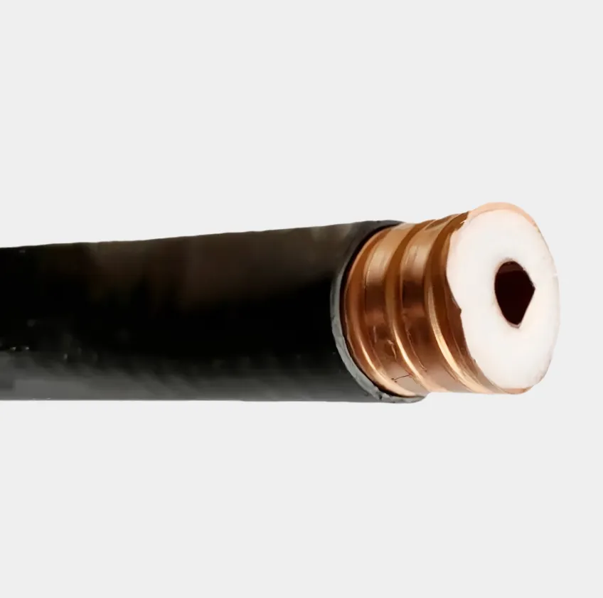
Testing coaxial cable is a critical process to ensure its performance, integrity, and suitability for applications such as television broadcasting, internet connectivity, satellite communications, and CCTV systems. Coaxial cables, composed of an inner conductor, insulating dielectric, metallic shield, and outer jacket, can suffer from issues like signal loss, impedance mismatch, breaks, shorts, or interference, which degrade performance. Proper testing identifies these problems, allowing for repairs or replacements before deployment or during troubleshooting. The process involves several key steps and tools, each targeting specific aspects of cable health. Before beginning tests, visual inspection is the first step. Examine the entire length of the cable for physical damage: check for cuts, cracks, or kinks in the outer jacket, which can expose the shield to moisture or interference. Inspect connectors (e.g., F type, BNC, N type) for corrosion, bent pins, or loose fittings, as these are common sources of signal loss. Ensure the connector is properly crimped or screwed on, with no gaps between the connector and the cable jacket, which can allow signal leakage. Any visible damage may warrant replacement or repair before proceeding with electronic testing. The next step is testing for continuity, which verifies that the inner conductor and shield are unbroken. A multimeter, set to the continuity or resistance mode, is used for this: touch one probe to the inner conductor of one end of the cable and the other probe to the inner conductor of the opposite end. A low resistance reading (near 0 ohms) indicates continuity; a high resistance (infinity) suggests a break in the inner conductor. Repeat the process for the shield, touching probes to the shield at both ends. This test confirms that the electrical path is intact, essential for signal transmission. Impedance testing is crucial, as coaxial cables are designed for specific impedance values (typically 50 ohms for data and RF applications, 75 ohms for video and CATV) to prevent signal reflection and loss. An impedance meter or a time domain reflectometer (TDR) measures the cable’s impedance along its length. A TDR sends a signal pulse down the cable and analyzes reflections: consistent impedance reflects minimal signal, while a mismatch (e.g., due to a damaged dielectric or connector) causes a significant reflection, indicating the location and severity of the issue. For example, a TDR reading showing a spike at 10 meters suggests an impedance mismatch at that point, possibly from a crushed dielectric or poorly installed connector. Signal loss, or attenuation, is measured using a network analyzer or a signal generator paired with a power meter. Attenuation increases with cable length and frequency, so testing should be done at the frequencies the cable will operate (e.g., 1 GHz for cable TV). Connect the signal generator to one end of the cable and the power meter to the other; the difference between the transmitted and received power indicates attenuation in decibels (dB). Compare results to the cable’s specifications—excessive attenuation may indicate a damaged dielectric, water ingress (which increases loss), or a poor connector. For example, a 100 foot RG 6 cable should have ~6 dB loss at 1 GHz; a reading of 12 dB suggests a problem. Testing for shorts is another important step, as a short between the inner conductor and shield causes signal failure. Using a multimeter in resistance mode, touch one probe to the inner conductor and the other to the shield at the same end of the cable. A low resistance reading indicates a short, which may be caused by a damaged dielectric allowing contact between the conductor and shield, or a faulty connector. Shorts can also occur at splices, so test each splice individually if the cable has multiple segments. Interference testing checks for electromagnetic interference (EMI) or radio frequency interference (RFI) that can corrupt signals. A spectrum analyzer connected to the cable detects unwanted signals within the operating frequency range. Alternatively, in a live system, observe for visual artifacts (e.g., snow on a TV screen) or audio noise, which indicate interference. This is particularly important for cables routed near power lines or industrial equipment, as EMI/RFI can penetrate poorly shielded cables. For long cables or those installed in walls, an OTDR (optical time domain reflectometer) is not used for coaxial cables, but a TDR is the equivalent tool, as mentioned, to locate faults without physical access. After repairs or installations, retesting all parameters ensures the cable meets performance standards. Documentation of test results, including dates, equipment used, and readings, provides a baseline for future comparisons, aiding in troubleshooting recurring issues. In summary, testing coaxial cable involves visual inspection, continuity checks, impedance measurement, attenuation testing, short detection, and interference analysis, using tools like multimeters, TDRs, power meters, and spectrum analyzers to ensure reliable signal transmission in its intended application.
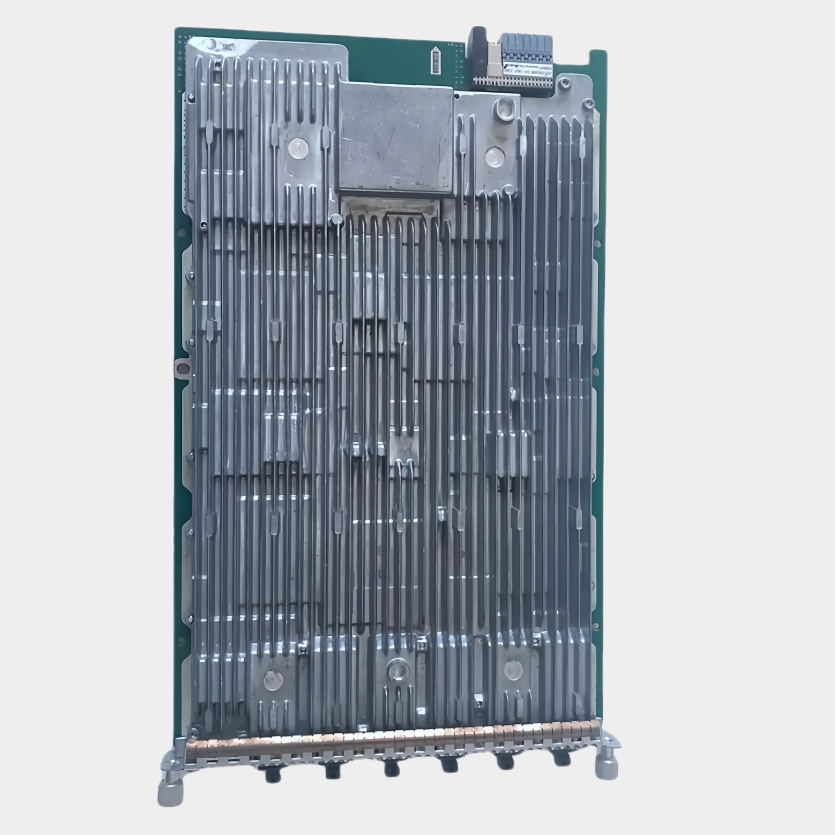
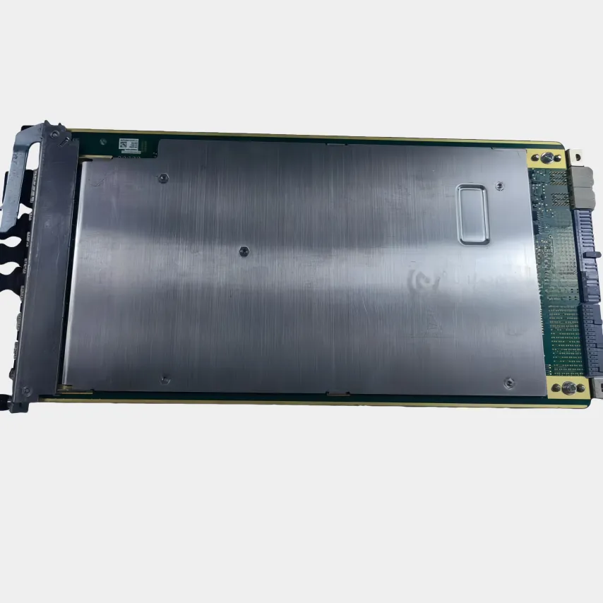
Hebei Mailing Communication Equipment Co., Ltd. offers high-quality RRU, BBU, and communication infrastructure solutions. Specializing in stable, high-strength equipment for global telecom, military, aerospace & industrial sectors. Trusted delivery worldwide.