
Frequency-Dependent Loss Mechanisms in 5G Coaxial Cable Performance
Skin Effect and Dielectric Losses Across Sub-6 GHz and mmWave Bands
When working at higher frequencies, coax cables just can't perform as well because of how nature works. The skin effect pushes RF currents toward the outer parts of conductors, which makes them act like they have higher resistance. Copper gets worse fast as frequencies climb, dropping about 40% in conductivity when moving from 3.5 GHz all the way up to 28 GHz. At the same time, materials inside the cable start absorbing more energy. Foam polyethylene loses around 0.5 dB per meter at 6 GHz, but switching to fluorinated ethylene propylene cuts that loss down by about 30% in those tricky millimeter wave ranges since it doesn't waste as much energy. All these combined losses really mess with signal quality in big MIMO systems, especially hurting beamforming precision past 24 GHz where there's barely any room for error anymore. System designers often find themselves fighting against shrinking margins of safety as frequencies keep rising.
Coaxial Cable Construction Choices That Define 5G Signal Integrity
Conductor Purity, Foam PE vs. FEP Dielectrics, and Shielding Architecture Trade-offs
The performance of coaxial cables in 5G systems really comes down to three main construction factors. Let's start with the conductor material. Oxygen free copper (OFC) is preferred because it cuts down on resistive losses. This matters a lot at millimeter wave frequencies since the skin effect pushes current into just a thin layer near the surface. Next up we have the dielectric material selection. There are tradeoffs here. Foam polyethylene works well for frequencies under 6 GHz with lower signal loss, but when pushing toward 28 GHz, fluorinated ethylene propylene (FEP) becomes better despite costing about 30% more according to RF Component Journal from last year. The third element is shielding. Multi layer designs like foil braid foil combinations typically reach over 95% coverage, which makes a big difference against electromagnetic interference in crowded installations. Tests in real world conditions show that cables using FEP instead of PE suffer around 15% less signal degradation at 24 GHz frequencies.
50 μ Impedance Consistency and Its Role in Minimizing 5G Base Station Reflection
Keeping 50 ohm impedance within a tight +/- 0.5 ohm range is really important to cut down on signal reflections in those 5G base station connections. Small issues matter here too. When the conductor size isn't consistent or there are gaps in the dielectric material, it raises something called voltage standing wave ratio or VSWR. And this problem gets worse as signals travel through all those antenna feeds in an array. Take a look at what happens when VSWR hits 1.5 to 1 at around 3.5 GHz frequencies. According to some industry reports from last year, this simple mismatch can actually drop the effective radiated power by about 20%. That's significant. Good manufacturing practices help maintain steady impedance levels even as cables get longer or temperatures change. This leads to return losses below -20 dB which makes a big difference for signal quality and beam alignment in those massive MIMO setups that modern networks rely on so heavily these days.
Environmental and Installation Challenges to Coaxial Cable Reliability in Real-World 5G Networks
EMI Resilience: Shielding Effectiveness in Dense Urban 5G Environments
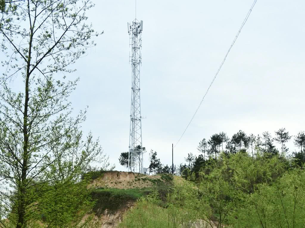
Coaxial cables really struggle with electromagnetic interference in crowded city areas where 5G antennas sit right next to power lines and all sorts of industrial machinery. The RF fields just keep overlapping everywhere, which messes up signal quality particularly bad on those shared utility poles or when multiple cables are clustered together on rooftops. Shielding made from both braided copper and aluminum foil can cut down on this interference by around 40 to 60 decibels, which helps maintain those important signal-to-noise ratios we need for good performance. When companies skip these shields, the drop in data throughput gets really noticeable in places with heavy interference such as busy train stations or downtown business areas where dozens of signals are bouncing around at once.
Physical Degradation Factors: Humidity, UV Exposure, Bending Radius, and Mechanical Stress
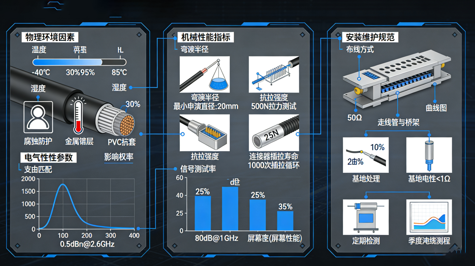
Outdoor 5G installations expose coaxial cables to multiple environmental stressors that accelerate aging and impair performance:
- Humidity: Moisture ingress corrodes conductors and degrades dielectric insulation, increasing attenuation by up to 15% (PTS, 2023); weatherproof jacketing and hermetically sealed connectors are mandatory in coastal or high-humidity regions.
- UV exposure: Unstable polyethylene sheaths will become brittle and crack after 2-3 years of sunlight exposure; UV stable compounds can extend their lifespan by about 70%.
- Bending radius: Tight bending can cause deformation of the dielectric core, resulting in local impedance mismatch and micro reflection, which is particularly destructive to millimeter wave signals.
- Vibration and Mechanical Stress: Wind loading and pole-mounted strain fatigue connectors over time; stainless-steel strain reliefs cut connector failure rates by 34% in high-traffic areas.
Robust installation practices—including adherence to minimum bend radii, use of UV-rated conduits, and proper strain relief—are not optional enhancements but foundational requirements for long-term reliability in real-world 5G networks.