 ×
×
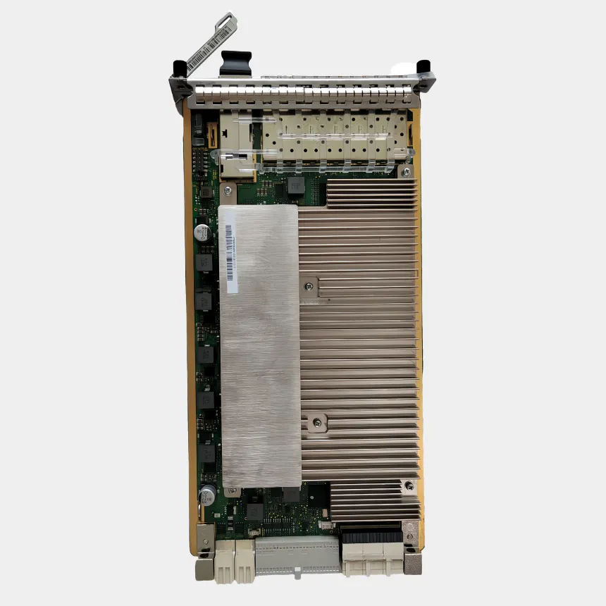
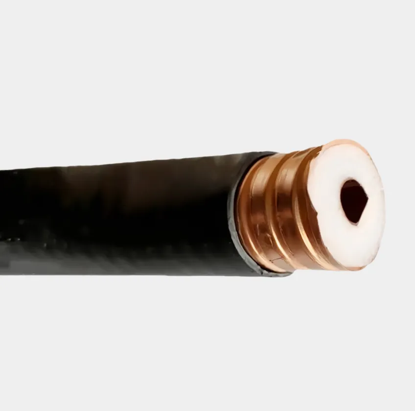
Optical transceiver and fiber matching solutions are critical in ensuring optimal performance and reliability in fiber optic networks, as mismatched components can lead to signal loss, increased bit error rates (BER), and reduced transmission distances. These solutions involve selecting transceivers and fiber cables that are compatible in terms of core size, mode (single mode vs. multimode), wavelength, and connector type, tailored to specific application requirements. Single mode fiber (SMF) has a small core (9μm) and is designed for long distance transmission (up to 100km or more) using transceivers operating at wavelengths of 1310nm, 1550nm, or 1610nm. SMF is paired with transceivers using laser diodes (e.g., DFB or EML lasers) that emit narrow, focused beams, minimizing dispersion. For example, a 10G SFP+ transceiver operating at 1550nm is ideally matched with G.652D SMF for metro or long haul networks, leveraging low attenuation at this wavelength. Multimode fiber (MMF), with larger cores (50μm or 62.5μm), is used for short distances (up to 550m) and paired with transceivers using VCSEL or LED light sources at 850nm or 1300nm. OM3 and OM4 MMFs, optimized for 850nm, are matched with 10G, 40G, or 100G transceivers (e.g., QSFP28) for data center interconnects, as their bandwidth distance product supports high speed transmission over short links. Connector compatibility is another key aspect. Transceivers with LC connectors are commonly matched with LC terminated fibers, ensuring low insertion loss, while SC or ST connectors may be used in specific industrial or legacy systems. Angle polished connectors (APC) are preferred for SMF links using wavelengths sensitive to back reflection (e.g., 1550nm), as they reduce return loss compared to ultra physical contact (UPC) connectors. Wavelength matching is essential to avoid excessive attenuation. For instance, 850nm transceivers should not be used with SMF, as MMF is optimized for this wavelength, and vice versa. WDM (Wavelength Division Multiplexing) transceivers require precise matching with fiber that supports the specific wavelength grid (e.g., ITU T G.694.1 for C band), ensuring that channels do not interfere with each other. Power budget analysis is part of matching solutions, calculating the total allowable loss (transceiver output power minus receiver sensitivity) and ensuring that fiber attenuation, connector loss, and splice loss do not exceed this budget. For example, a 40G QSFP+ transceiver with a power budget of 10dB should be paired with fiber links having total loss ≤10dB, considering factors like cable length and number of connectors. Environmental factors also influence matching. Industrial transceivers rated for 40°C to 85°C are matched with ruggedized fiber cables (e.g., armored) for outdoor or harsh environments, while data center transceivers (0°C to 70°C) use standard MMF or SMF. Proper documentation and testing (e.g., using an OTDR or power meter) verify that the transceiver fiber match meets specifications, ensuring network performance and reducing troubleshooting time.
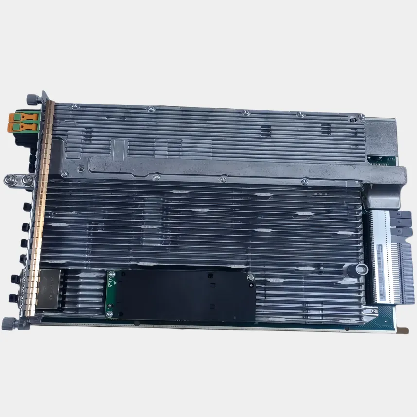
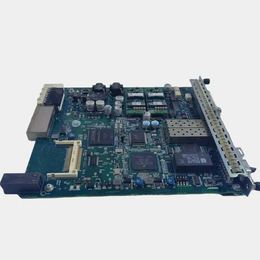
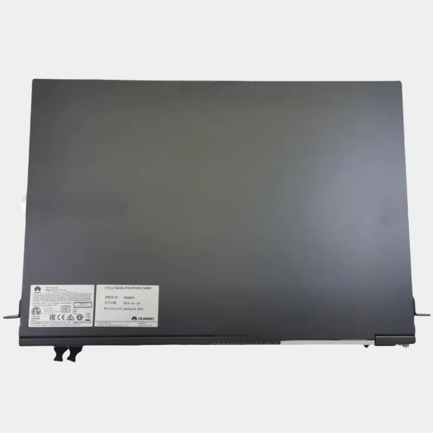
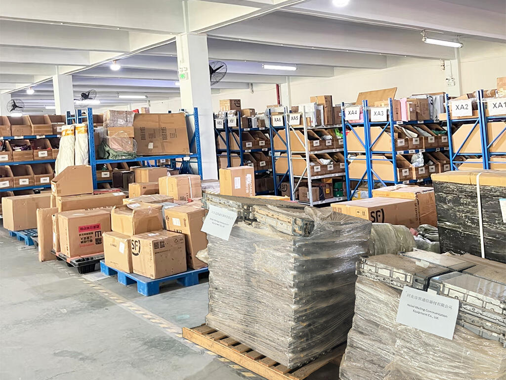
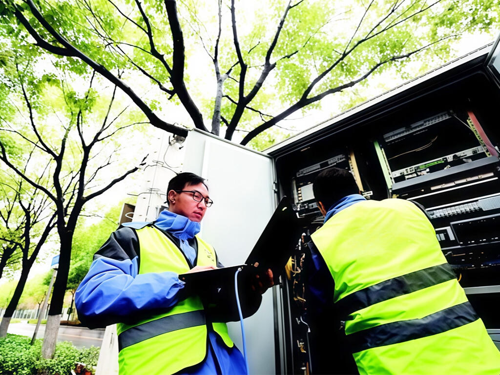
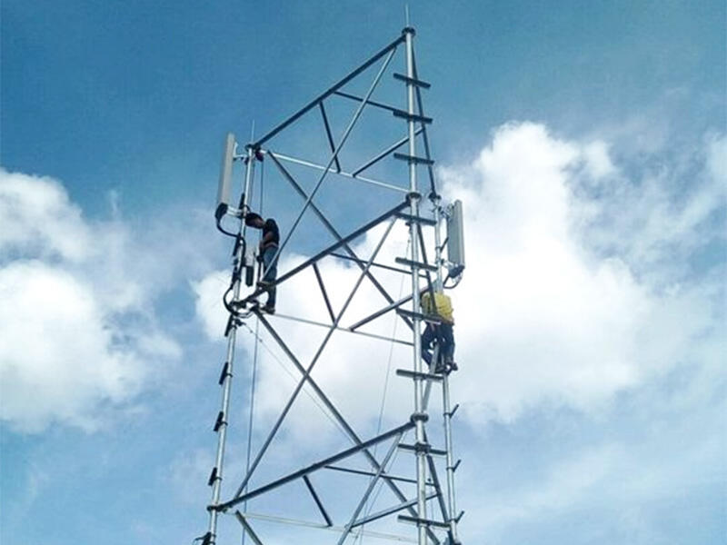
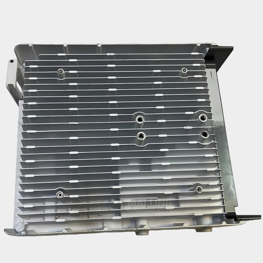
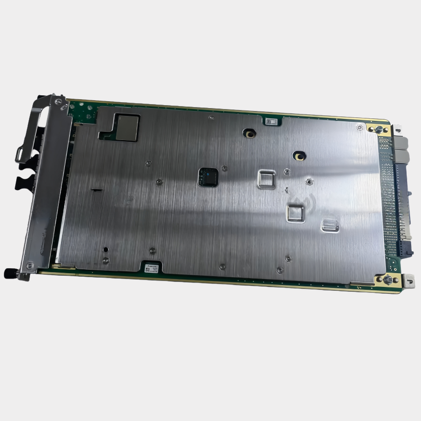
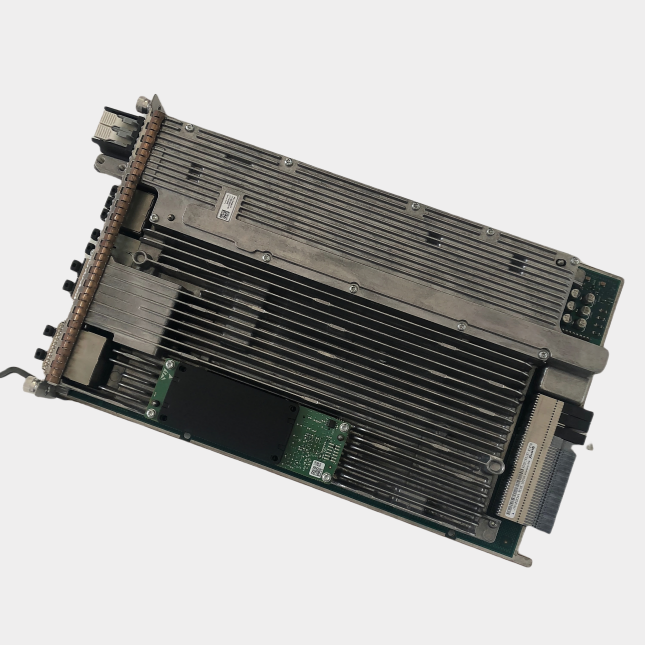
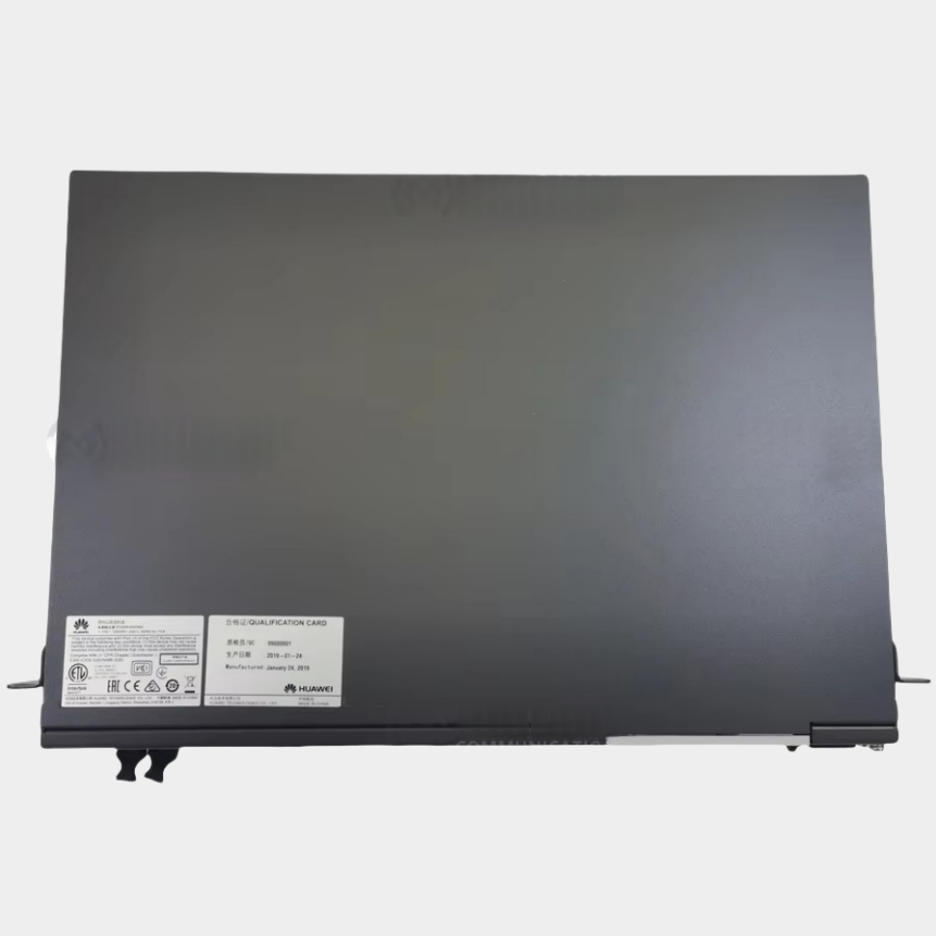
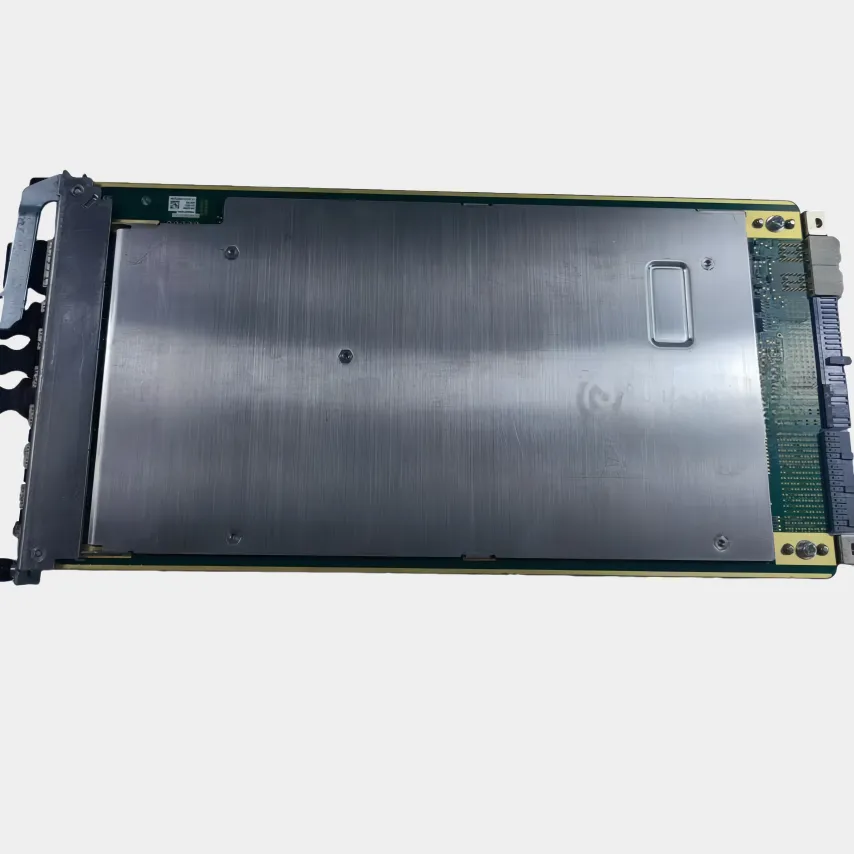
Hebei Mailing Communication Equipment Co., Ltd. offers high-quality RRU, BBU, and communication infrastructure solutions. Specializing in stable, high-strength equipment for global telecom, military, aerospace & industrial sectors. Trusted delivery worldwide.